

 English
 Deutsch
 简体中文
简体中文
Author: FTM
Date: May 27, 2026
How Does Sand Casting Work? Process & Parts Explained
Sand casting works by packing a sand mixture around a pattern of the desired part, removing the pattern to leave a cavity, pouring molten metal into that cavity, and breaking away the sand mold once the metal solidifies. It is the world's oldest and most widely used metal casting process, accounting for roughly 70% of all metal castings produced globally by weight. Sand casting can produce parts ranging from a few grams to over 100 tons, in nearly any metal, with minimal tooling cost compared to other casting methods. The trade-off is dimensional tolerance and surface finish — sand cast parts typically achieve tolerances of ±0.03 to ±0.06 inches per inch and surface roughness values of 250–500 Ra (µin), which is coarser than die casting or investment casting but entirely adequate for a vast range of structural and mechanical applications.
The Sand Casting Process: Step by Step
Sand casting follows a repeatable sequence of steps that transforms raw sand and molten metal into a finished part. Each step has specific technical requirements that determine the quality of the final casting.
- Pattern making: A pattern — an exact replica of the desired part, typically oversized by a shrinkage allowance of 1–2.5% depending on the metal — is fabricated from wood, plastic, aluminum, or urethane foam. The pattern includes draft angles (usually 1–3 degrees per side) to allow clean removal from the sand without disturbing the mold cavity walls.
- Mold preparation: The pattern is placed in a two-part box called a flask (the cope on top, the drag on the bottom). Sand is packed firmly around the pattern in each half. For green sand casting — the most common method — the sand mixture is 85–95% silica sand, 4–10% bentonite clay as a binder, and 2–5% water. The clay and water create plasticity that holds the mold shape when the pattern is withdrawn.
- Pattern removal: The flask halves are carefully separated and the pattern is drawn out, leaving a precise negative impression of the part geometry in the sand. A parting compound applied to the pattern before ramming prevents sand adhesion during removal.
- Core setting (if required): For parts with internal cavities — such as hollow tubes, engine ports, or cored holes — pre-formed sand cores are placed into the mold cavity before closing. Cores are made separately from chemically bonded sand (no-bake, shell, or cold box process) and supported by core prints — projections on the pattern that create recesses in the mold wall where core ends rest.
- Gating system creation: Channels cut or formed into the sand — called the gating system — guide molten metal from the pouring cup through the sprue (vertical channel), along runners (horizontal channels), and into the mold cavity through ingates. Risers (reservoirs of extra metal) are also positioned at thick sections to feed molten metal into the part as it shrinks during solidification, preventing shrinkage porosity.
- Mold assembly and pouring: The cope and drag are reassembled and clamped or weighted to prevent the hydrostatic pressure of the molten metal from lifting the cope off during pouring. Metal is poured at the correct temperature — typically 1,250–1,500°C for cast iron and 650–750°C for aluminum alloys — smoothly and continuously to avoid turbulence, which can trap gas or erode the mold walls.
- Cooling and solidification: The filled mold is left undisturbed while the metal cools. Cooling time ranges from minutes for small aluminum parts to many hours for large iron or steel castings. Premature disturbance causes hot tears, distortion, or incomplete solidification.
- Shakeout: Once sufficiently cooled, the sand mold is broken apart — mechanically vibrated on a shakeout screen — to free the casting. The sand is collected, reconditioned by adding fresh clay and water, and recycled back into production. In high-volume foundries, 90–95% of green sand is reclaimed and reused.
- Cleaning and finishing: The raw casting is cleaned by shot blasting or tumbling to remove adhering sand, then the gating system (sprue, runners, risers) is cut off and ground flush. Final steps may include heat treatment, machining to tolerance, and surface treatment depending on the application.
Key Sand Casting Parts and Their Functions
Understanding the individual components of a sand casting setup clarifies how the process controls metal flow, heat distribution, and final part quality. Each sand casting part serves a specific engineering purpose.
| Sand Casting Part | Location | Function |
|---|---|---|
| Pattern | Removed before pouring | Creates the mold cavity shape; includes shrinkage allowance and draft |
| Flask (Cope & Drag) | Surrounds the entire mold | Rigid frame that contains the sand during ramming, handling, and pouring |
| Parting Line | Interface between cope and drag | Defines the split plane of the mold; appears as a seam on the finished casting |
| Core | Inside the mold cavity | Creates internal voids, holes, and undercuts that the external pattern cannot form |
| Pouring Cup / Basin | Top of the mold | Receives molten metal from the ladle; reduces turbulence at the sprue entrance |
| Sprue | Vertical channel in cope | Carries metal downward from the pouring cup to the runner system |
| Runner | Horizontal channel at parting line | Distributes metal from the sprue base to one or multiple ingates |
| Ingate | Entry point into cavity | Controls flow rate and direction of metal entering the mold cavity |
| Riser (Feeder) | Above thick sections of cavity | Reservoir of liquid metal that feeds the casting as it shrinks during solidification |
| Vent | Small channels in cope | Allows gases and steam to escape the mold during pouring, preventing porosity defects |
| Chaplets | Inside cavity supporting cores | Small metal supports that hold cores in position against buoyancy forces during pouring |
Types of Sand Casting Processes
The term "sand casting" encompasses several distinct process variants, each suited to different production volumes, part complexities, and accuracy requirements. Choosing the right process type is as important as the casting design itself.
Green Sand Casting
The most common and lowest-cost sand casting method. "Green" refers not to color but to the moisture content of the sand — typically 2–5% water activates the bentonite clay binder. Green sand casting is the default process for high-volume gray and ductile iron production, with many automotive foundries running fully automated green sand lines producing thousands of castings per day. Sand is immediately recyclable after shakeout. Limitations include lower dimensional accuracy than chemical-bonded processes and potential for moisture-related gas defects if mold moisture is not controlled.
No-Bake (Air-Set) Sand Casting
Sand is mixed with a two-part chemical binder (such as furan resin or phenolic urethane) that cures at room temperature through a chemical reaction rather than heat or moisture. No-bake molds are harder and more dimensionally stable than green sand molds, yielding tolerances approximately 25–50% tighter than green sand. This process is preferred for large, complex parts — industrial pump housings, large valve bodies, and machine tool components — where dimensional accuracy justifies the higher binder cost and longer mold preparation time.
Shell Molding (Croning Process)
Fine silica sand coated with thermosetting phenolic resin is dropped or blown onto a heated metal pattern (175–370°C), forming a thin shell 10–20mm thick that cures in 10–30 seconds. The two shell halves are bonded together with adhesive to form the complete mold. Shell molding produces surface finishes of 125–250 Ra (µin) and dimensional tolerances of ±0.010 inches — significantly better than green sand. It is commonly used for automotive camshafts, crankshafts, connecting rods, and other medium-volume precision parts.
Lost Foam Casting (Full Mold Process)
An expanded polystyrene (EPS) foam pattern — identical to the final part — is buried in loose, unbonded dry sand. When molten metal is poured, it vaporizes the foam, taking its exact shape. No mold removal is needed, and complex geometries with internal features that would require multiple cores in conventional sand casting can be produced as a single foam pattern. Lost foam casting is used extensively for aluminum cylinder heads, intake manifolds, and complex iron engine blocks — General Motors has produced over 15 million cylinder heads using this process.
Vacuum (V-Process) Casting
Dry, unbonded sand is held in place against a thin plastic film draped over the pattern by vacuum pressure rather than a chemical binder. After pouring and solidification, the vacuum is released and the sand flows away freely — no shakeout required. V-process casting achieves surface finishes of 150–300 Ra and excellent dimensional repeatability, with the added advantage of producing almost no waste gases during pouring, making it one of the cleanest sand casting methods environmentally.
Materials That Can Be Sand Cast
One of sand casting's most significant advantages over competing processes is its material versatility. Sand casting is compatible with virtually every castable metal and alloy, including those with high melting points that would destroy permanent metal molds.
| Metal / Alloy | Pouring Temp. (°C) | Common Sand Cast Parts | Key Advantage |
|---|---|---|---|
| Gray Cast Iron | 1,300–1,450 | Engine blocks, brake drums, machine bases | Low cost, excellent machinability, vibration damping |
| Ductile (Nodular) Iron | 1,350–1,480 | Crankshafts, gears, differential housings | High strength and ductility vs gray iron |
| Aluminum Alloys | 680–780 | Cylinder heads, intake manifolds, pump housings | Low weight, good corrosion resistance |
| Bronze / Brass | 950–1,100 | Valve bodies, marine hardware, bushings, propellers | Corrosion resistance, bearing properties |
| Carbon / Low-Alloy Steel | 1,550–1,650 | Rail components, mining equipment, structural parts | High strength, weldability, heat treatable |
| Stainless Steel | 1,480–1,600 | Pump impellers, food processing equipment, valves | Corrosion and heat resistance |
| Magnesium Alloys | 650–750 | Aerospace housings, lightweight structural parts | Lightest structural casting metal |
Common Sand Casting Defects and How They Are Prevented
Sand casting defects account for an estimated 5–10% of production in well-run foundries and up to 20–30% in poorly controlled operations. Understanding defect causes is essential to designing process controls that minimize scrap rates.
Porosity (Gas and Shrinkage)
Porosity is the most common sand casting defect, appearing as voids within the solidified metal. Gas porosity forms when hydrogen or moisture-generated steam is trapped in the melt before solidification. Shrinkage porosity forms when molten metal contracts as it solidifies and insufficient liquid metal is available to fill the gap. Prevention involves controlling sand moisture content below 4%, degassing the melt with nitrogen or argon purging, and correctly sizing and positioning risers.
Sand Inclusions and Cold Shuts
Sand inclusions occur when loose sand eroded from mold or core surfaces is carried into the casting by turbulent metal flow. Cold shuts form when two streams of metal meet in the mold and fail to fuse properly — typically caused by metal that has cooled too much before filling the cavity, or a gating system that splits flow poorly. Proper gating design with controlled fill velocities (below 0.5 m/s at the ingate for iron), adequate mold pre-heating for aluminum, and well-compacted sand all reduce these defects.
Hot Tears and Distortion
Hot tears are cracks that form in the casting during solidification when thermal contraction is constrained by the mold or core. They are most common in thin sections adjacent to thick ones, and in metals with wide solidification ranges like aluminum bronze. Design solutions include adding fillets (minimum 3–5mm radius) at section transitions, increasing core collapsibility, and adjusting solidification sequence through chills or riser placement.
Sand Casting Tolerances, Surface Finish, and Dimensional Capabilities
Setting realistic dimensional expectations before committing to sand casting prevents costly redesigns. The process has well-established capability limits that vary by process type, metal, and part size.
| Process | Linear Tolerance (in/in) | Surface Finish Ra (µin) | Min. Section Thickness |
|---|---|---|---|
| Green Sand | ±0.030–0.060 | 250–500 | 3–5 mm |
| No-Bake / Air-Set | ±0.020–0.040 | 200–400 | 4–6 mm |
| Shell Molding | ±0.010–0.020 | 125–250 | 2–3 mm |
| Lost Foam | ±0.010–0.025 | 125–250 | 2.5–4 mm |
| V-Process | ±0.010–0.020 | 150–300 | 3–5 mm |
For reference, investment casting typically achieves ±0.005 inches per inch and 63–125 Ra, while high-pressure die casting reaches ±0.002–0.005 inches per inch — both at substantially higher tooling costs. Sand casting tolerances are fully adequate for most structural parts, housings, and brackets that require machining of critical interfaces anyway.
Sand Casting vs Other Casting Processes: When to Choose Sand
Sand casting is not always the optimal process choice. Understanding where it excels and where it falls short relative to alternatives prevents costly process selection mistakes.
Sand Casting Advantages
- Lowest tooling cost of any casting process: A simple wooden or plastic pattern for green sand casting can be made for $500–$5,000. A comparable die casting die costs $20,000–$200,000. This makes sand casting the only economical option for prototype quantities, short runs (under 500 parts), and very large parts where die tooling is impractical.
- No practical size limit: Sand casting produces the largest metal castings made by any process. The largest single sand castings — massive frames for hydroelectric turbines, ship propellers, and press frames — weigh over 100 tons and could not be produced by any other method.
- Compatible with all castable alloys: Including high-melting-point ferrous alloys (steel, stainless steel, high-chromium iron) that would erode or destroy aluminum or zinc die casting tooling within a single shot.
- Complex internal geometry via cores: Sand cores allow internal passages, cavities, and features that cannot be extracted from a permanent mold — critical for engine blocks, valve bodies, and hydraulic manifolds.
When to Choose a Different Process
- High volume + tight tolerance + thin walls → Die casting: For aluminum or zinc parts in quantities above 10,000–50,000 with wall thicknesses under 2mm and tolerances tighter than ±0.010 inches, high-pressure die casting has a lower per-part cost despite higher tooling investment.
- Complex geometry + fine surface finish → Investment casting: Parts with thin walls, fine detail, and near-net-shape requirements (eliminating most machining) are better served by investment casting despite its higher per-piece cost.
- Simple rotational parts → Centrifugal casting: Pipes, tubes, rings, and cylindrical bushings are produced more economically and with better mechanical properties (due to centrifugal segregation) by centrifugal casting than by sand casting.
Industries and Products That Rely on Sand Casting
Sand casting is deeply embedded in the manufacturing supply chain of multiple major industries. Many components that appear in finished products every day began as sand castings.
Automotive Industry
The automotive industry is the largest consumer of sand castings globally, accounting for approximately 35–40% of total foundry output by weight. A single internal combustion engine contains dozens of sand cast components: the engine block, cylinder head, intake manifold, exhaust manifold, crankshaft (in many designs), differential housing, transmission case, brake calipers, and wheel hubs. A typical passenger car contains 150–250 lbs of iron and aluminum sand castings.
Industrial Machinery and Pumps
Machine tool bases, pump casings, compressor housings, valve bodies, impellers, and hydraulic manifolds are extensively sand cast in cast iron, steel, and bronze. The combination of complex internal geometry (pump volutes, valve chambers), large size, and low-to-medium production volumes makes sand casting the optimal process for the vast majority of industrial fluid handling equipment.
Aerospace and Defense
While aerospace precision parts often use investment casting or machined forgings, sand casting produces many structural airframe components, gearbox housings, nacelle structures, and ground support equipment parts in aluminum and magnesium alloys. Sand casting is also the primary process for large artillery components, vehicle armor brackets, and naval hardware where part size and alloy requirements exceed investment casting capabilities.
Construction, Mining, and Energy
Crusher jaws, mill liners, excavator teeth, pipeline fittings, manhole covers, and wind turbine hubs are among the high-wear, high-strength sand cast parts used in these industries. A single wind turbine hub — typically cast from ductile iron — can weigh 15–30 tons and requires the dimensional stability and internal soundness that only a well-engineered no-bake sand casting process can reliably deliver at this scale.
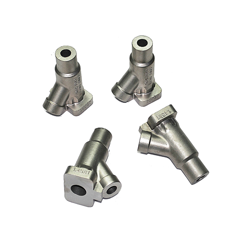
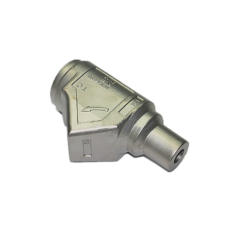
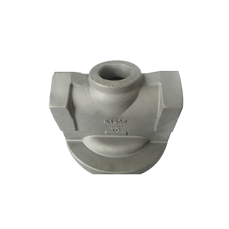
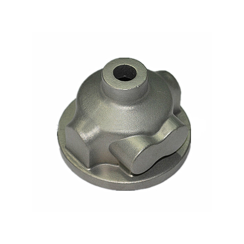
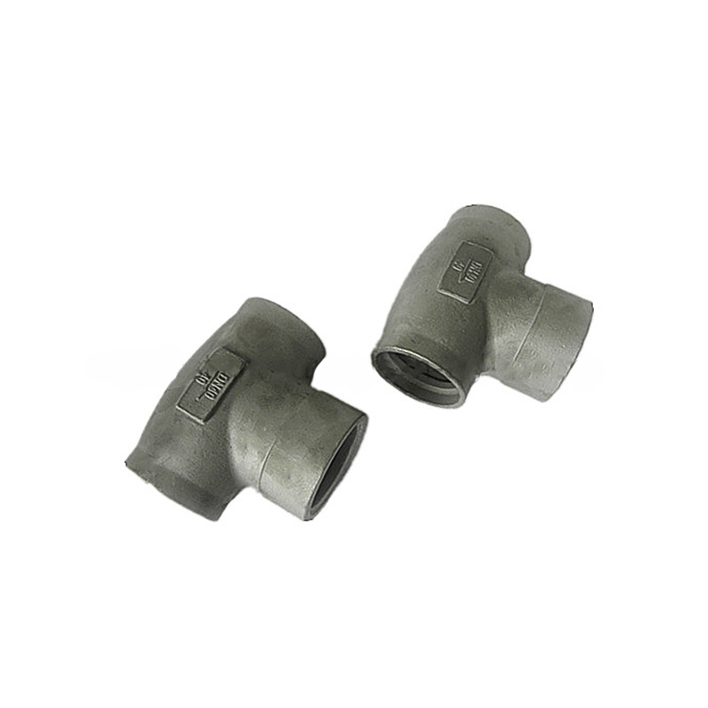
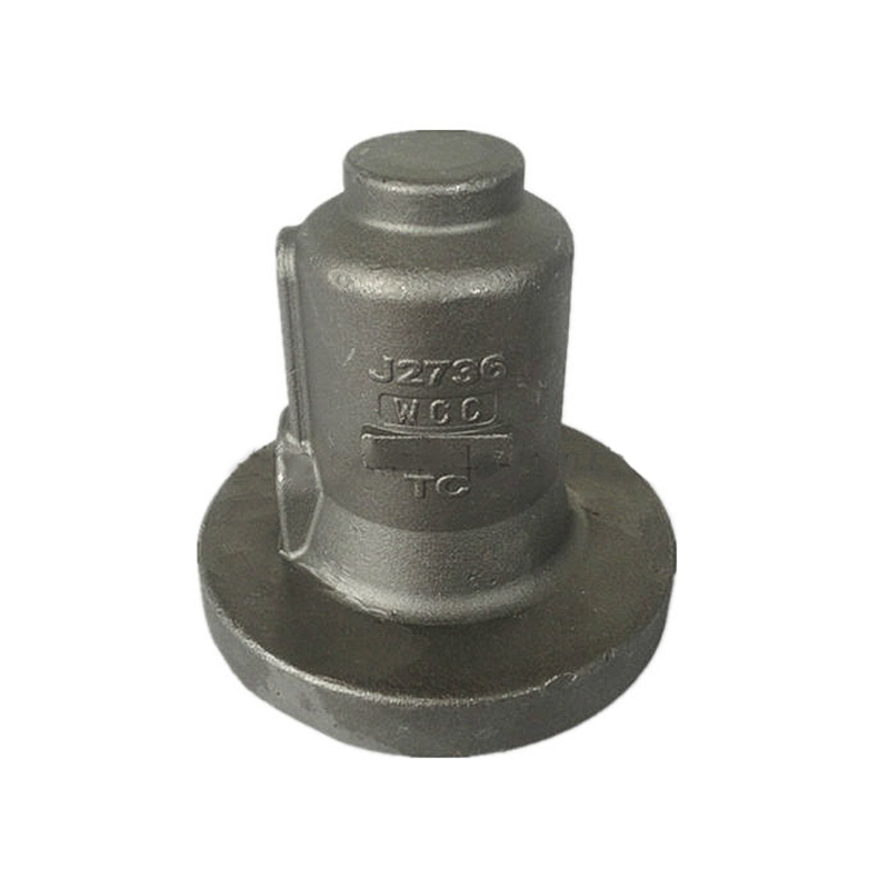
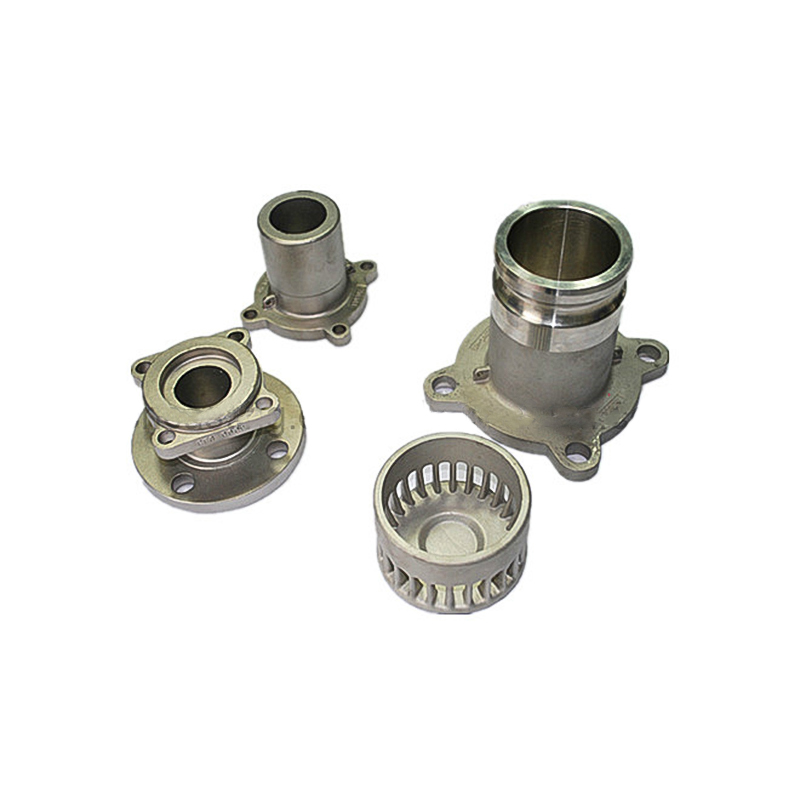
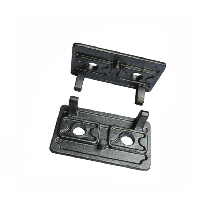
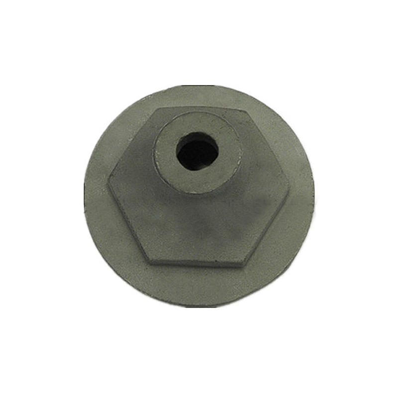
Selected Bearing Display

Contact Information
- Tel:+86-574-88067800/88067900
- Fax:+86-574-88067400
- Phone:+86-13967874638
- E-Mail:master@nbyifei.com
Products Links
Products Links
- Agricultural Machinery Casting Parts
- Auto Casting Parts
- Brass Die Casting Parts
- Casting Bucket Tooth And Accessory
- Container Casting Parts
- Investment Casting Parts
- Machinery Casting Parts
- Mining Machinery Casting Parts
- Railway And Train Casting Parts
- Sand Casting Parts
- Stamping & Forging Parts
- Valve Casting Parts
Contact Us
Copyright ©
Ningbo Hansheng Machinery Parts Co.,Ltd. All Rights Reserved
 Custom Die Castings Manufacturers
